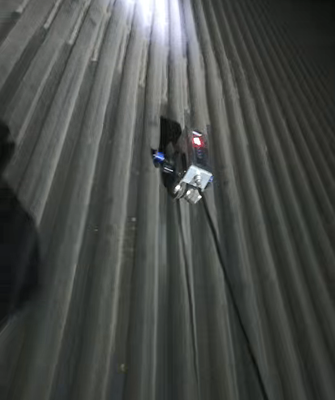
TG-M90 Automated EMAT Wall Thickness Measurement Inspection Crawler
Structural Description
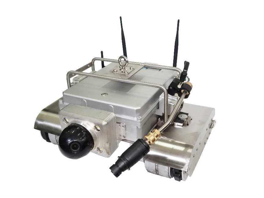
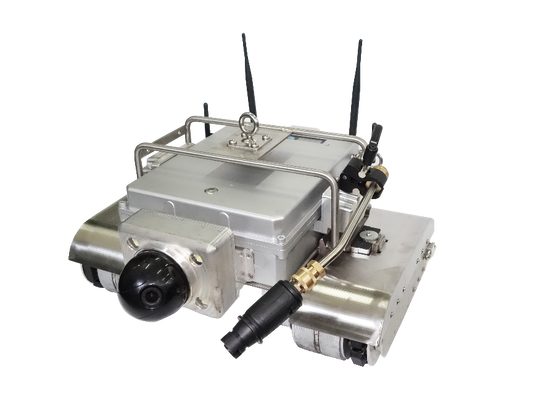
1. Robot Body Structure

2. Control System Composition
2.1 Control Box
2.2 Control System
2.3 Management System Software
The intelligent inspection robot management system software is integrated into the terminal control system, enabling real-time image and thickness measurement data monitoring, robot control, path planning, and export of thickness measurement data and trajectory details.
Instructions for Use
3.1 Installation Instructions
① Cable connection:
a) First, connect the control box to the robot body using a winding wheel ;
b) Next , connect the charging port of the control box to the power supply ;
c) Both the control box and the robot are equipped with batteries, which can be used either by connecting to a power source or by charging and using them wirelessly.
② Installation of positioning device:
1) First, install the two black N-type 2.4G UWB positioning antennas at the antenna interface on the top of the robot body;
2) Next, install two black SMA interface 2.4G WIFI antennas on the antenna interfaces on both sides of the robot body;
3) Finally, the base stations were installed, one at each of the four corners of the water-cooled wall area to be tested.
③Installation of fall arrestor :
The fall arrestor must be suspended high and used low. The two fall arrestors are suspended on the pipe clamps on both sides of the water-cooled wall, and the other end of the fall arrestor is connected to the support above the robot.
Before use, please be sure to check that the fall arrestor is securely connected and functioning properly , and test the lock 2-3 times (test locking method: pull the safety rope out at normal speed, it should make a "click" sound. Pull the safety rope hard, it should lock. When you release it, the safety rope should automatically retract. If the safety rope does not retract completely, pull out a small portion of the safety rope and then release it ). If any abnormality is found, stop using it immediately.
2. Operating Instructions
2.1 Power -on test
① The robot auxiliary lighting switch is located on the robot body. Before starting work, turn on the light switch first.
② Click the " Switch " button at the bottom right of the control box. The three green indicator lights on the control box, "Walk", "Manual", and "Power On", will light up, indicating the initial state and normal power-on.
3.2.2 Robot walking
①Keyboard control
The robot defaults to manual control mode upon startup. Selecting " Walk " enables fast movement , while selecting " Test " enables slow movement . The robot can be controlled to move forward, backward, turn , and stop using the physical directional keys on the control box .
② Software control
Click "Robot Control" on the homepage of the management system software to enter the operation interface. You can control the robot to move through the software and display the robot's movement position synchronously in the coordinate system.
2.3 Path Planning
Click on "Path Planning" on the homepage of the management system software to set the robot's walking route. The robot can then move automatically along the preset path, and the robot's coordinates will be displayed on the page.
2.4 Visual inspection
① The visual inspection system mainly consists of two parts. It adopts an integrated design, enabling simultaneous output of three panoramic views from different directions and one close-up view, supporting panoramic linkage functionality. The pan-tilt-zoom (PTZ) of the close-up camera is adjusted and zoomed via a control box, placing the inspection area in the center of the image. The infrared illumination radius can reach up to 10 meters. The maximum resolution and frame rate can reach 1920×1080@30fps.
② The main system software can display environmental images and thickness measurement data in real time. Clicking the pan-tilt control button on the software interface controls the camera's 360° rotation and electric focus, meeting the requirements for magnified observation of local areas. Clicking " Number of Window Separations " allows you to select to display images captured by one or more cameras .
③ The lighting switch is located on the robot body . When turned on , it makes it easy to observe the robot's operating status and route in dim environments .
④ During inspection , you can click "Capture Image" or " Start Recording" to take photos and videos of defects. After the inspection is completed , export the image information, thickness measurement data, and trajectory details.
3.2.5 Electromagnetic ultrasonic thickness measurement
① Click the "Test" button on the control box, and the robot will enter the thickness measurement mode.
② The robot body is equipped with an ultrasonic thickness measurement module, which does not require coupling agent and allows the workpiece surface to have coking, floating rust and unevenness of less than 2 mm ; it can continuously and quickly measure the wall thickness and output it stably to the control box.
③ During the inspection operation, the thickness sensor of the robot body can adapt to water-cooled wall tubes of different specifications, and realize continuous thickness measurement of water-cooled wall tubes of different diameters.
④ Thickness measurement data can be displayed on the control box screen in real time, and the thickness measurement data also supports historical data query.
3.2.6 Marking function
When an anomaly is detected, paint can be sprayed onto the pipe wall surface using the marking function to mark the fault point, so that the fault point can be quickly located and repaired.
3.2.7 Precision positioning system
The robot chassis is equipped with a pipe recognition module. When the robot's movement direction is in the positive X-axis direction, the count increases by 1 for each pipe it passes; when the robot's movement direction is in the negative X-axis direction, the count decreases by 1 for each pipe it passes. This counting module can locate the pipe position corresponding to each set of thickness measurement data, achieving accurate positioning of thickness measurement data and movement trajectory.
3.2.8 High-pressure water cleaning
The robot body is equipped with a high-pressure water cleaning module to perform high-pressure water cleaning on the spiral section, straight section, and inclined ash hopper of the water-cooled wall. The pressure can reach up to 10 MPa , which is used to remove surface dust and coke, laying the foundation for subsequent inspection operations. The cleaning switch is located on the high-pressure water pump.
high-pressure water gun and water pipe are fixed to the front right side of the robot by a bracket, and the water pipe is connected to the water pump . When the high-pressure water pump is turned on, the water gun moves with the robot along the water-cooled wall tube bank to clean the tube wall surface.
3.3 Faults and Solutions
① Electrical fault
Robots may experience malfunctions such as circuit board damage, motor failure, and cable breakage. These malfunctions can cause the robot to malfunction or fall, such as the robot becoming uncontrollable, the control box not responding when powered on, the control box failing to receive power, no image transmission, and thickness measurement data not being fed back normally .
Solution : Inspect the damaged part and replace it.
②Inaccurate thickness measurement data
Cause : The magnetic powder from the water-cooled wall may have contaminated the probe , leading to inaccurate thickness measurements.
Solution : Clean the thickness gauge probe. If the problem persists , perform multiple tests to check if the thickness gauge itself is faulty.
③ Software failure
System software may experience program crashes, data loss, or software update failures, which may cause the robot to malfunction or be unable to connect to the network.
Solution : Reinstall the software, restore backup data, and check network connectivity.
4. Technical parameters and performance indicators
Robot body
Dimensions: 490mm*483mm*249mm
Weight: 27.5 kg
Maximum load: 40kg
Power supply: DC48V, 12Ah (AC220V)
Camera: 1920*1080
Maximum walking speed: 5m/min
Thickness measurement walking speed: 2m/min
Positioning accuracy: ±2cm
Can turn on the spot
Waterproof rating: IP65
Incline angle: 120°
Cleaning pressure: 10 MPa
Thickness measurement parameters
Measurement range: 0.8~300mm
Thickness measurement accuracy: 0.1mm
5. Packing List
|
Serial Number
|
Component Name
|
quantity
|
Serial Number
|
Component Name
|
quantity
|
|
1
|
Robot body
|
1 unit
|
10
|
High-pressure water gun, water hose
|
1 set
|
|
2
|
control box
|
1 unit
|
11
|
robot
Main packaging box
|
1
|
|
3
|
control box
48V charger
|
1
|
12
|
High-pressure water gun packaging box
|
1
|
|
4
|
Ontology
24V charger
|
1
|
13
|
Fall arrestor packaging box
|
1
|
|
5
|
2-meter connecting cable
|
1 item
|
14
|
mouse
|
1
|
|
6
|
Connecting cable + reel
|
1 set
|
15
|
Location base station charger
|
2
|
|
7
|
UWB positioning base station
|
4
|
16
|
Product manual +
Product Packing List
|
1 copy
|
|
8
|
Fall arrestor
|
2 sets
|
1 7
|
Product Certificate
|
1 copy
|
|
9
|
High-pressure water spray device
|
1 unit
|
18
|
Product Warranty Card
|
1 copy
|


 Your message must be between 20-3,000 characters!
 English